Nizo lightmeter 2.7V voltage regulator

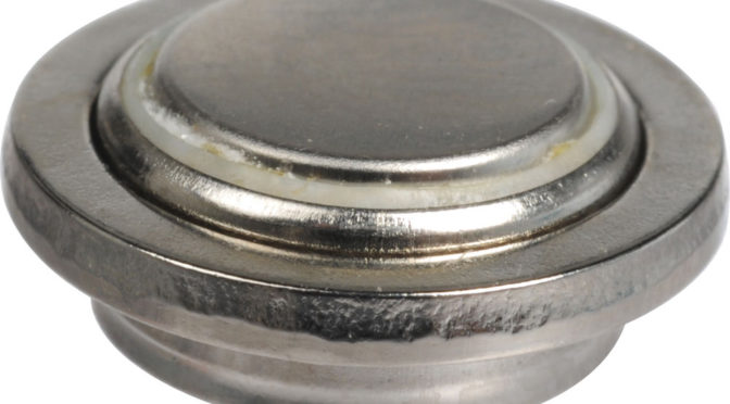
Loads of Braun Nizo super 8 camera owners, especially of the 400, 500 and 800 series have the problem of not being able to get their hands on 2 button cell batteries of 1.35V each. Together feeding the light meter circuitry with 2.7V. The original PX625 Mercury button cell batteries aren’t produced anymore, I guess for environmental reasons. They provided a 1.35V voltage. Nowadays the 625 batteries provide 1.5V.

The problem is that we have had quite some reports of owners using 2 cells of 1.5V each, thus providing 3Volts to the circuitry. This would give different light meter results so ideally one finds a way to provide 2.7V to the circuit without having to worry about button cell batteries in the Nizo.

There are quite a few solutions to the problem, such as using more environment friendly Weincell batteries (Zinc-Oxide), that do provide 1.35V but are quite expensive and tend to die rather quickly if not properly stored. Other solutions involve using Zener diodes and creating adapters from PX625 batteries that hold the zener diode and can house a smaller cell battery.

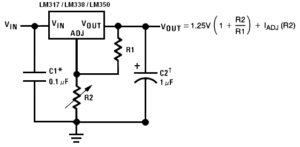
The solution proposed here is building a simple voltage regulator circuit existing of the LM317 voltage regulator IC, a 500 Ohm trimmer, a 220 Ohm resister, a 1mF electrolyte capacitor and a 100nF capacitor.  The circuit is shown below:

voltage-regulator

Soldered together the circuit looks like this:

nizo-lightmeter-voltage-regulator

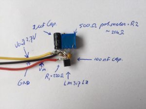
Do connect this circuit to some power source like a 9V battery and adjust the trimmer such that you can measure 2.7V at the yellow output lead (use a multimeter).

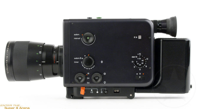
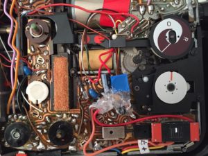
One way of adding the circuit to your Nizo camera is to first hot-glue all leads and solder to isolate them, open up the side of the camera (4 screws), solder GND and Vin and the 2.7V output to the correct contacts on the Nizo circuit board and place the circuit as shown below (Nizo 801 case but other cameras should be similar):

nizo-inside

When done correctly the side cover will just be able to still fit and you can screw it back on with the 4 screws. Do not forget to remove any remaining 625 button cell batteries from the camera or you can get failures.

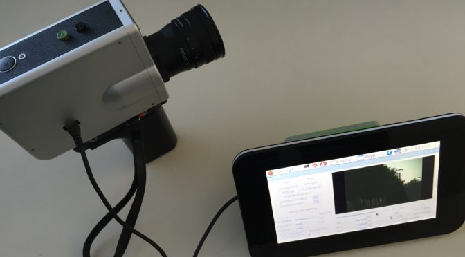
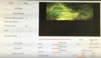
Then, switch on the power of the Nizo and test the light meter by pressing the appropriate button and you will see a perfect indication of the meter on the number ‘8’  of the light meter.

Currently we are exploring a different way to add this circuit to the Nizo camera and that is to solder it together just tight enough that it will actually fit within the original button cell housing. One would have to take out the metal strip at the bottom of that housing, then 2 little holes are available. Through one of these holes one can put GND and Vin leads (have to be soldered to the right contact points within the camera, and the 2.7V output lead can be guided into the camera using the other hole. This method will be tested and instructions and pictures will be provided in a next post.

Code update 4 – improving buffering

Over the last couple of weeks a lot of spare time went into improving the code that controls the image capturing. The main bug to address was that the image capturing would ‘hang’ after a certain amount of time when capturing say round 10 seconds or more of 720p 12 bit images.

We revisited the code and the multi-threaded buffering algorithm. Putting the buffer and the code that empties the buffer on a separate thread, away from the main user interfacing window thread dramatically improved the performance. The ‘hanging’ capturing was solved except for the fact that at some times the output of Ximea API messages can still interfere with the code, which is at the capturing stage pushing all boundaries of the raspberry pi 3. When run with an open terminal window the problem is solved but we will ‘silence’ the API output further in order to completely solve the issue.

The only other point to note is that when capturing 720p resolution (the highest option) and at 12 bit, the image capture buffer fills up quite rapidly as the large RAW images take time to be written to microSD card. When ~300 images are in the buffer the raspberry pi sort of gives up and starts ‘sputtering’. Waiting long enough for the buffer to empty solves the situation but you will lose images.

Best options in this ‘best mode’ are to capture shorter shots. Also scaling back to 8 bit RAW dramatically slows down filling up of the buffer. Another option is to move to 540p at 12 bit.

A final ‘disturbing’ issue is that the Ximea camera every now and then ‘disconnects’ and throws an error. The ConnectCam button needs to be pressed to reset the connection and filming can resume. Whether this is a bad USB cable issue or something else will be investigated.

Digital Super 8 outdoors test

We took the wearable control unit and the Digital Super 8 cartridge outside for some portable testing.

At dusk we shot the grapes growing in the garden. First part is dark at 200 ASA but we also tested the autogain function that increases the CMOS sensor gain as necessary, leading to better brightness. At the cost of noise in the images of course.

We decided to not color correct the images, just take the 12 bit RAW images (as always) and do the gamma correction. But leaving brightness, saturation, contrast, red, blue and green in their default state. Pretty pleasing results, filmed with the Nizo 481 macro lense at dusk.


Code update – 2

During our last coding session we developed the ‘ConnectCam’ button. This button allows users to functionally re-connect the digital super 8 cartridge to the raspberry pi control unit.

This comes in handy in case the USB cable between control unit and cartridge gets accidentally disconnected or wasn’t connected before the control application was started. This will help users solve small issues that may lead to a ‘DS8 Cartridge not connected’ error messages in the application.

Black Edition Nizo 801 Macro

Last week we picked up a mint condition black edition Nizo 801 Macro super 8 camera. And it came packaged in an original Braun Nizo ‘Trickbox’, including working charger and power supply.

We’ll check the camera and service it. Also apply the mod where we build in a voltage regulator circuit so the camera will not need 1.35V button batteries that are hard to come by.

Code development update

The code we develop for the Digital Super 8 cartridge has 2 major functions. One is to start up and control the cartridge and start and stop image capturing mode. In capture mode the cartridge will record RAW images as the user shoots with the Super 8 camera.

The other function is to post-process the captured images (color grading, brightness and contract corrections and gamma correction) and to ‘develop’ the captured digital super 8 images into a video file (either uncompressed or MPEG compressed).

One key change currently being worked on is to split the application into 2 separate ones. One for controlling the cartridge, tweak settings and start/stop image capture mode. The other for post-processing, so after filming is done this application is a small but fully standalone image processor and video rendering app.

Another major step is to develop a ‘re-connect’ function to give the application better performance for cases where due to whatever reason the usb cable (between cartridge and external module) is disconnected.